INTRODUCTION
Since its opening in 2010, the Cal Poly’s Simpson Strong-Tie Material Demonstration Laboratory has been used for multiple activities by the College of Architecture and Environmental Design. Currently, the bottom floor is used for Construction Management laboratory classes. These classes allow students to practice construction techniques at full scale.
The size of these projects is problematic when assemblies need to be moved or when the finished structure needs to be removed from the building. For example, one class builds a small portion of a traditionally constructed house. The roof for this structure is constructed on the ground and lifted into place atop walls. Currently, the lifting is accomplished with the student’s brute force and a forklift, which is ineffective, dangerous, and requires advance coordination with the Facilities Department. Installing a crane overhead would allow projects to be maneuvered safely.
PROJECT MANAGEMENT

Figure 1: The Three Project Priorities.
At the start of a project, it is important to define the client’s priorities so the team knows what to focus on. A project can only optimize two of the three priorities:
- Time
- Cost
- Quality
For example, a project can have a short timeline and low cost but the deliverable won’t be good quality. On this project, time and quality were priorities. Time was required because the project had to be finished in a quarter. Quality was required because the calculations were going to be used for the internal Cal Poly approval process.
STRUCTURAL ANALYSIS
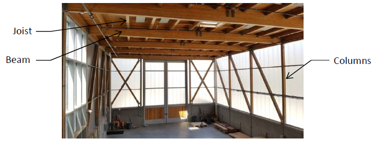
Figure 2: Interior of Simpson Strong-Tie Building.
The plans were obtained through Cal Poly’s construction drawing archive, Web-Planroom. The existing building has a timber framed roof (heavy timber joists and glulam beams) supported on pre-engineered lumber parallam columns. These columns are supported on a concrete wall which rests on a continuous spread footing. The interior of the building can be seen in figure 2.
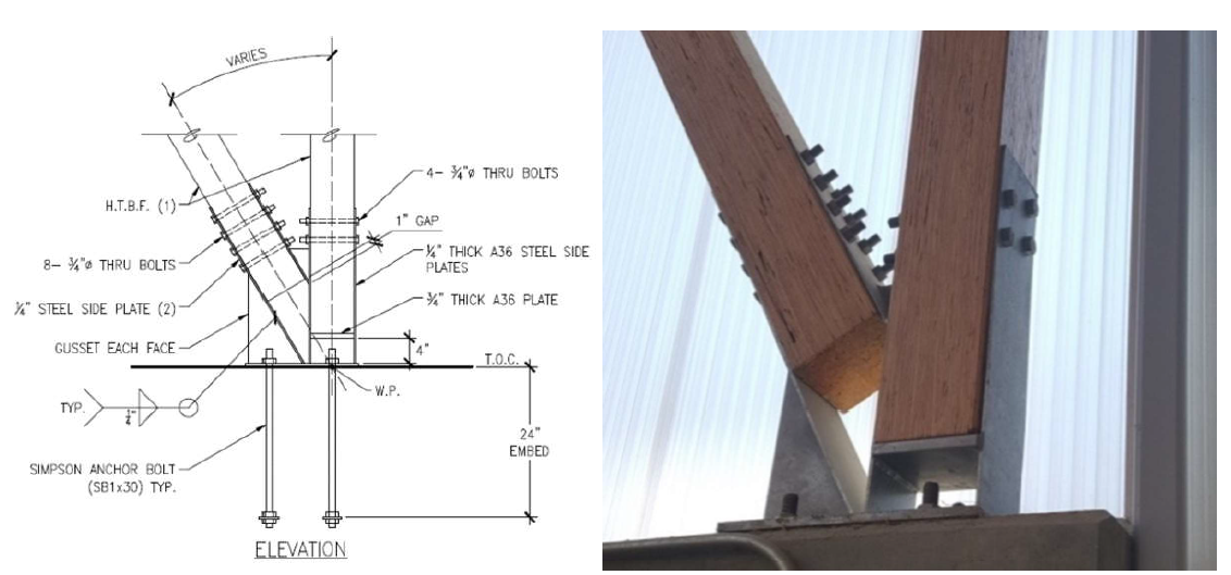
Figure 3: Drafted Detail and Existing Connection.
The connections were also inspected visibly and appeared to match the details in the as-built drawings.
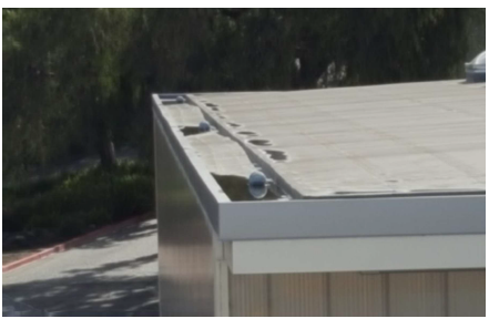
Figure 7: Extent of Pooling Relative to Roof Area.
The water is not deep and the nets protecting the down sprouts seem clear of debris, which limits the possible depth of puddling. The sitting water is a result of the roof sloping slightly toward the edge of the roof instead of in toward the drainpipes. The puddling only occurs near the downspouts and only within the gutter channels on the edge of the roof. The limited extent of the pooling can be seen in Figure 7.
ESTIMATE EXISTING CAPACITY
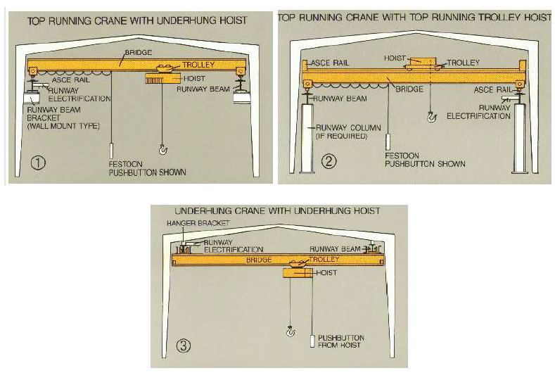
Figure 8: Possible Methods for Attaching Overhead Crane to Structures.
The addition for this project was an overhead crane. There are several ways to add an overhead crane to a building as shown in figure 8:
- Attaching the crane runways to the columns.
- Installing separate columns (stanchions) that would support the crane completely apart from the existing structure.
- Attaching the runways to the roof.
NEW LOADING
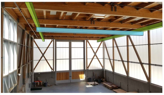
Figure 9: Approximate Location of Crane Members: Runways in Green, Bridge Girder in Blue.
The ideal location has the minimum impact on the existing systems. For example, the Simpson Strong-Tie building has fire sprinklers installed above where the crane members will be installed. To minimize interference with water coverage, the runways should be placed directly below the first row of sprinklers as shown in figure 9.
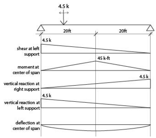
Figure 11: Influence Lines for Bridge Girder.
In this project, the moving load was the crane housing and hoist, applied on the bridge girder. Influence lines were found for the moment at the center, the shear at the end, the deflection, and the reactions at the ends. The maximum values from the shear, moment and deflection influence lines were used to size the bridge girder (see figure 11). The vertical reactions were also found and used to load the glulam beams.
FINAL DESIGN
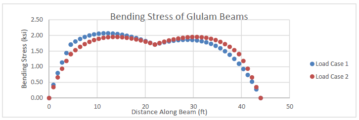
Figure 13: Bending Stress on Tapered Glulam Beams (load cases correspond.
A spreadsheet was made (in Microsoft Excel) that calculated the section properties at increments along the beam. The bending stress was checked at each increment. The graph shown in figure 13 illustrates how the stress changes along the beam.
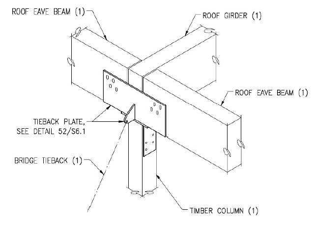
Figure 14: Glulam Beam to Column Connection.
The glulam beams are connected to the columns by a bearing connection, shown in figure 14. The governing capacity for this connection was the axial capacity of the parallel strand laminated column. The axial capacity of the column was low because its large unbraced length makes it susceptible to buckling. The column had just enough capacity to support the additional weight of the crane.

Figure 16: Final Connection Design.
A strap was added on each side of the connection that passes around the entire perimeter of the glulam, shown in figure 16. The strap will hold the layers of the glulam together, not allowing them to delaminate. The strap will need to be sized to accommodate the swelling and shrinking of the wood throughout seasonal humidity changes.
CONCLUSION
This report found the Simpson Strong-Tie building can support a 2-ton overhead crane. The report specifically investigated hanging the crane from the glulam beams. The type of crane considered was a two-ton hoist with the system specified by the vender, Dearborn Overhead Cranes (more information can be found in the crane quote in Appendix D). More specifically, the existing structure can support a hanger load of 7.8 kips, occurring four and a half feet away from the exterior wall on the glulam beams. While not investigated, supporting the crane on a separate column (stanchion) is also a viable option; however existing foundation coordination will have to be considered.
The capacity of the existing structure is governed by the axial capacity of the parallel strand laminated columns. The columns were originally designed to support a green roof. The green roof was never installed, creating enough extra capacity to allow the installation of the crane. After the installation of the crane the columns will be at capacity and will not have the ability to support additional loads, from either the load racks or any future additions including a green roof.
The connection design included in the report is suggested. It is mainly included to show the ability of the beam to support the crane. Connection sizing and redesign will likely be needed for the chosen crane.
The steps outlined in the project management section were sufficient for this small project. The project was completed on time. I gained experience working in an interdisciplinary team, especially on a project on a short schedule.
Hopefully the calculation package will contribute to Cal Poly Facility’s approval for overhead crane installation in the Simpson Strong-Tie building.
Source: California Polytechnic State University
Authors: Amy Poehlitz