ABSTRACT
The purpose of this project is to investigate a particular, undesirable cracking pattern in concrete tiltup panels that, until now, did not have a known definite cause. The cause of this cracking pattern is hypothesized to be due to shrinkage restraint of the concrete panels. The cracking under investigation occurs at the bottom corners of the TiltUp panels, suggesting that the base of the panel is restrained from shrinkage. This project models various components of TiltUp Construction that have potential for restraining the panels from shrinking. This project consists of the following main components.
The first aspect of this project was to investigate and become familiar with the means and methods of TiltUp Construction. To determine the potential shrinkage restraints on the panels, the connections and details associated with TiltUp must be thoroughly understood. This involved reviewing typical details of connections as well as contacting engineers and contractors in the field to determine the typical means and methods of TiltUp construction and construction sequencing.
Once typical construction practices were understood, the first shrinkage restraint investigated was the friction developed by the panel setting pads. Once the panel is ready to lift, it is set on grout pads or plastic shims, typically located at the ends of the panel. To determine the amount of restraint caused by friction, an experiment was conducted to determine the coefficient of static friction. Tests were run to find the coefficient of friction for concrete against grout, and concrete against plastic shims.
The third aspect of this project was to develop an effective computer model of stresses in TiltUp panels induced by shrinkage restraint. The goal of this model was to be able to run various scenarios, to determine the effects of panel concrete mix design, panel geometry, and construction sequencing.
The last aspect of this project was to collect enough data from the computer model to determine whether or not shrinkage restraint induces enough stress in the panel to initiate cracking, determine when the cracking would occur given construction sequencing, as well as determine if the cracking pattern matches the pattern seen out in the field.
Conclusions will have to be made on a case by case basis, but the panel specifications in this analysis were chosen from a Home Depot building in San Luis Obispo, CA, an asbuilt TiltUp project. After running about 70 different cases, it was discovered that the grout pads by themselves did not provide enough shrinkage restraint to initiate cracking in the panel. This led to further investigation of panel connections, specifically the panel to slab connection at the pour strip.
This paper concludes that when combining the shrinkage restraint from grout pad friction and pour strip reinforcement tension, there is potential for cracking in the panel. Even further, the cracking pattern determined from the computer model provides nearly an exact match to the actual cracks under investigation and measured in the field. Although this report provides evidence for potential cracking in TiltUp panels due to shrinkage restraint, recommendations for limiting the potential of cracking in panels will need to be made on a case by case basis.
HYPOTHESIS: SHRINKAGE RESTRAINT
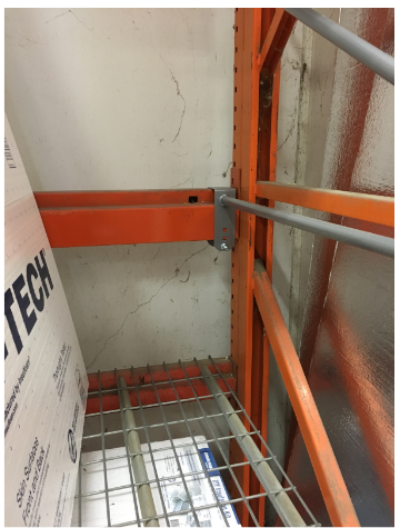
Figure 2.0 – Interior Panel Cracking at Home Depot, San Luis Obispo.
The cracking pattern indicates the location, amplitude, and direction of the stresses that induced cracking. This cracking pattern indicates that the highest stresses in the panel are located at the base, and are tension stresses because concrete only cracks under tensile stress. Perhaps the biggest indicator at first glance is to notice that these cracks occur on both sides of the panel, as can be seen in Figure 2.0. Any out of plane flexure or lifting cracks would only occur on one side of the panel.
POTENTIAL SHRINKAGE RESTRAINTS
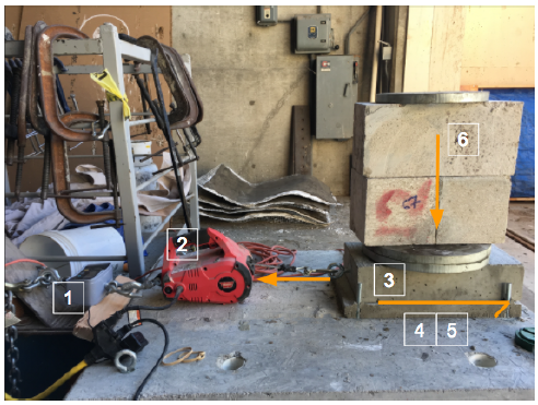
Figure 3.1: Friction Experiment Components 1. Load Cell 2. PullzAll 3. Precast concrete testing block 4. Grout Pad 5. Shim Pack 6. Additional Weight.
The load cell is attached to the material being pulled (concrete) as it rests on the grout pad. Once the pull begins, the load cell will determine the amount of tension force that is acting on the system. The load will continue to increase until it exceeds the friction force between the two surfaces and the material begins to slip. The force displayed on the load cell at the moment the system slips will be used to determine the coefficient of static friction in Figure 3.1.
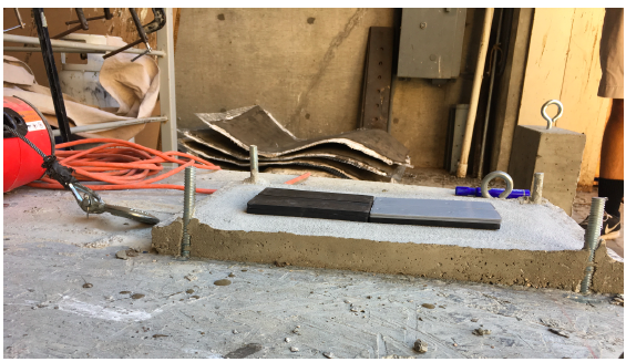
Figure 3.3 – Plastic Shim Pack Orientation and Set Up.
The highdensity plastic shims used in this experiment varied in thickness and were stacked 4” x 6” Super Shims , manufactured by MeadowBurke, for the purpose of bearing setting pads below tiltup panels. These shims typically come in various thicknesses so that the desired shim height can be desire by stacking shims. Figure 3.3 below shows the shim orientation and method of testing used in this experiment.
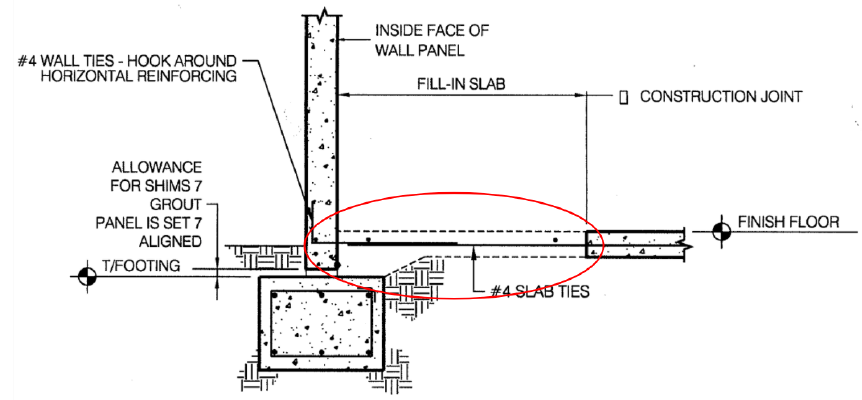
Figure 3.6 – Typical Panel to Slab Connection Detail (Ward).

Figure 3.7 – FBD of Pour Strip Shrinkage Restraint.
The rebar tying from the slab to the panel is not resisting the panel but rather just along for the “shrinkage ride” and provides negligible shear friction. However, the rebar in the pour strip parallel to the panel will resist this shrinkage and because this rebar is tied to the panel, the rebar in the pour strip will impose a force upon the panel as it displaces. The amount of rebar in the pour strip that is engaged due to the proximity of the panel has not been investigated but can be determined that at least one bar would be engaged. See Figure 3.6 and 3.7.
THE COMPUTER MODEL
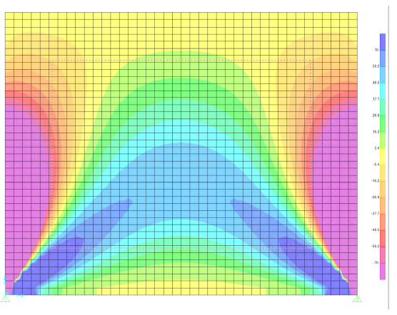
Figure 4.1 Stress Output in the ZZ Direction.
Below you can see the direct stress pattern output for the xx and zz direction in Figure 4.1. The output of the data has the convention that all positive numbers are in tension while all negative numbers are in compression and the scales for those values are to the right of the figures. The more blue colors represent zones of tension while the more purple colors represent zones of compression.
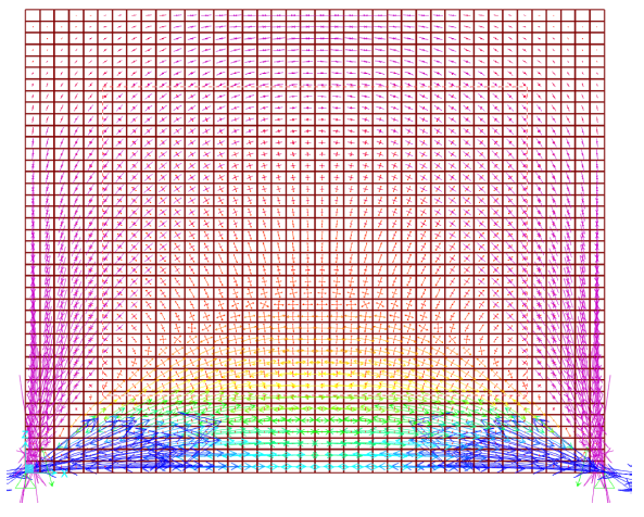
Figure 4.2 Principal Stress Direction.
As you can see from Figure 4.2 below there are various regions of the panel with different types of stresses. Large stress areas and small stress areas, various angles of combined stresses from 0 to 90 and zones of tension and compression. The bottom most region is where the xx stresses dominate the zz stresses encouraging the cracks to naturally travel vertically with small slants towards the edges of the panels depending on which side of center the crack initiates on.
The next graph and explanation below will demonstrate why construction sequencing can be so important for the construction of tilt up.
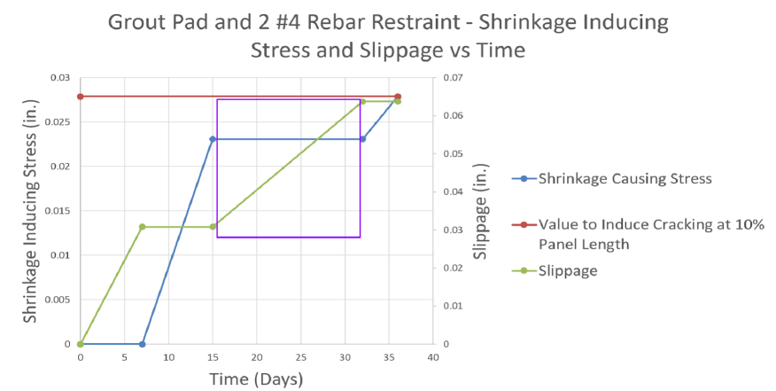
Please note that the graph above has two vertical axis values and scales. Being able to look at shrinkage inducing stress and slippage can be valuable because by adding up the value on the Shrinkage Inducing Stress axis at 36 days (0.279 inches) and the Slippage value at 36 days (0.0637 inches) we see that the total shrinkage value to induce cracking at 10% of the panel length occurs after a total shrinkage of 0.092 inches.
CONCLUSION
As we have seen from the experimental values in combination with the computer model results, cracks can initiate given that there is a pour strip restraint from a minimum of one #4 rebar in addition to friction restraint from a grout pad. Whereas, if a plastic shim pack is used, shrinkage cracking could be avoided or minimized. Another possible solution to reduce shrinkage that has been practiced is using multiple setting pads moved away from the panel joints towards the middle of the panel. Moving the setting pads in from the panel edge allows the setting pads to resist less shrinkage as well as force the stresses to rip through more concrete.
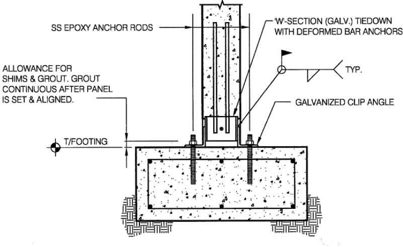
Figure 5.0 Welded Foundation to Connection (Ward).
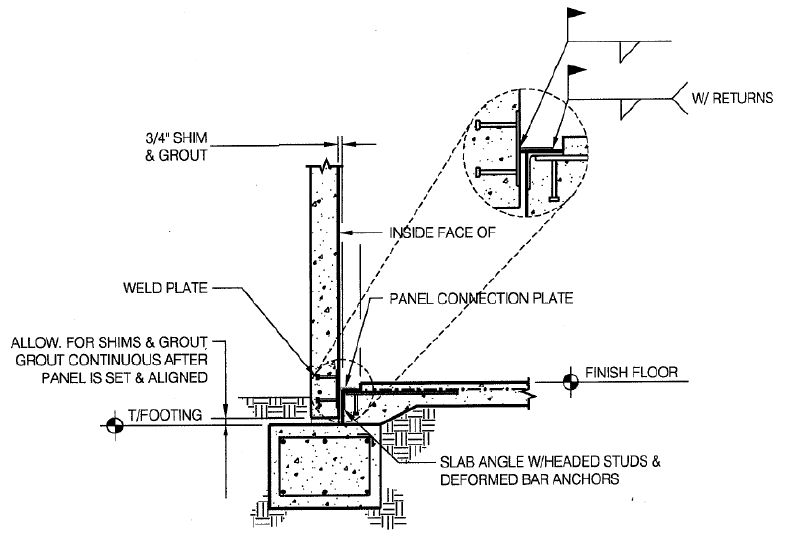
Figure 5.1 Welded Foundation Connection (Ward).
Due to panel shrinkage over time, the earlier these restraints are installed, the more likely cracking is to take place. Although recommendations need to be made on a case by case basis, it can generally be recommended to avoid providing rigid restraints to the ends of panels, due to they will almost certainly crack. Below Figure 5.0 and 5.1 are typical details suggested by TiltUp Concrete Association for panel to foundation anchorage, and potentially can increase the likelihood of shrinkage cracking within the panel.
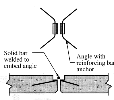
Figure 5.2 Welded Panel to Panel (Ward).
Having a welded condition between the panel and foundation looks and functions very similarly to what the condition from a paneltopanel connection used to be. In the past, paneltopanel connections used to be welded as can be seen in Figures 5.2.
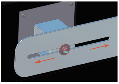
Figure 5.4 SlottedBolt Concept.
Once building owners started to take notice of these cracks, contractors and engineers were under pressure to develop new ideas and considerations for how panels should be connected with each other. Slottedbolt connections between panels have been introduced and brought into practice in order to reduce this type of restraint as can be seen in Figure 5.4.
Source: California Polytechnic State University
Authors: Stewart Hooks | Jack Robinson
